Final Project - Macropad with Analog Knob Input
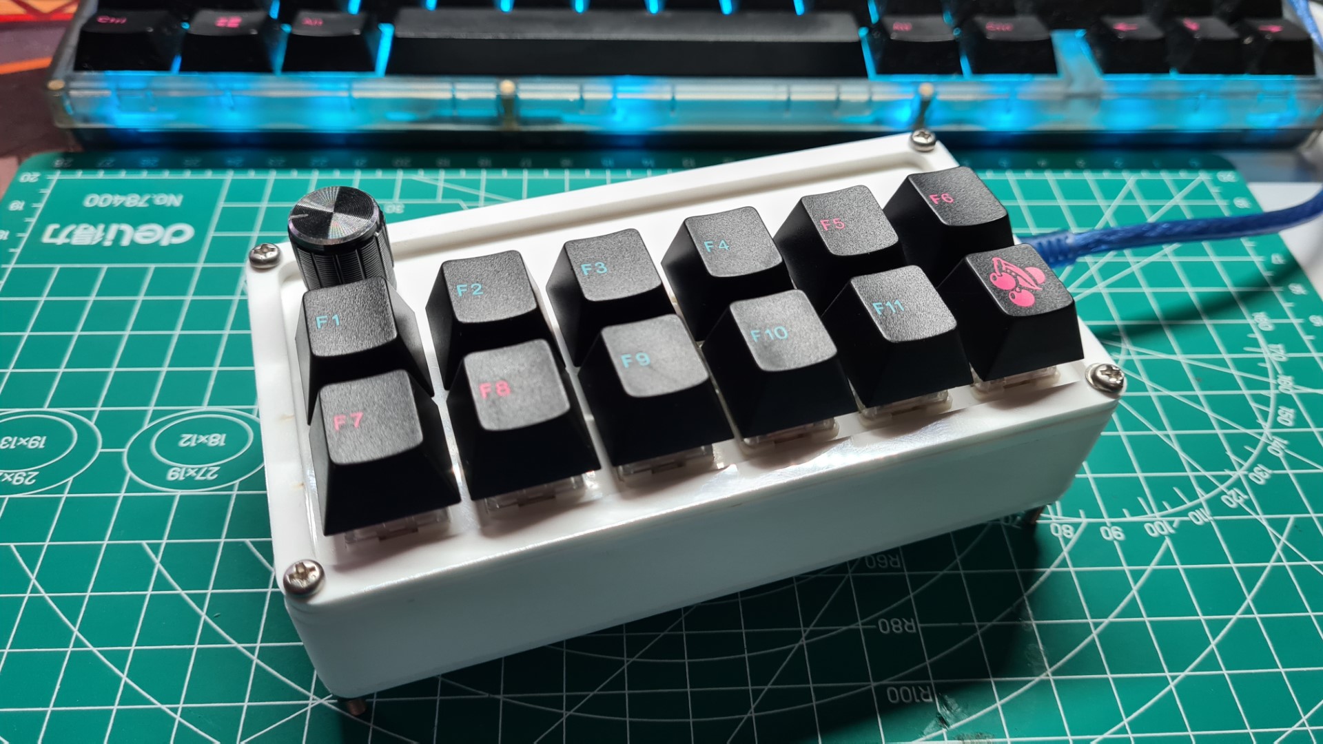
For the Final Project for this module, I decided to make a Macropad. This Macropad will have 12 keys with 11 keys acting as input for F1-F11 keys. The other key together with the analog knob will be used to control volume. The
Bill of Materials
| # | Material/Item | Quantity |
|---|---|---|
| 1 | Pro Micro | 1 |
| 1 | Gateron Brown Mechanical Switches | 6 |
| 1 | NovelKeys x Kailh BOX Thick Clicks - Navy | 6 |
| 1 | White Acrylic Plate | 1 |
| 1 | M3 x 40 screws | 4 |
3D Design Process
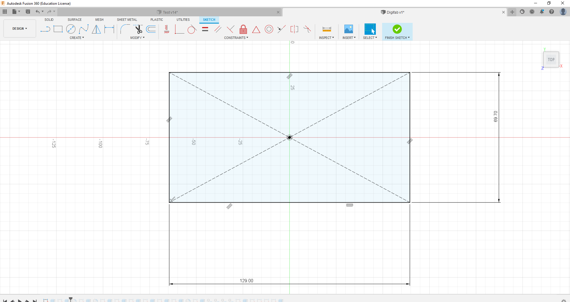
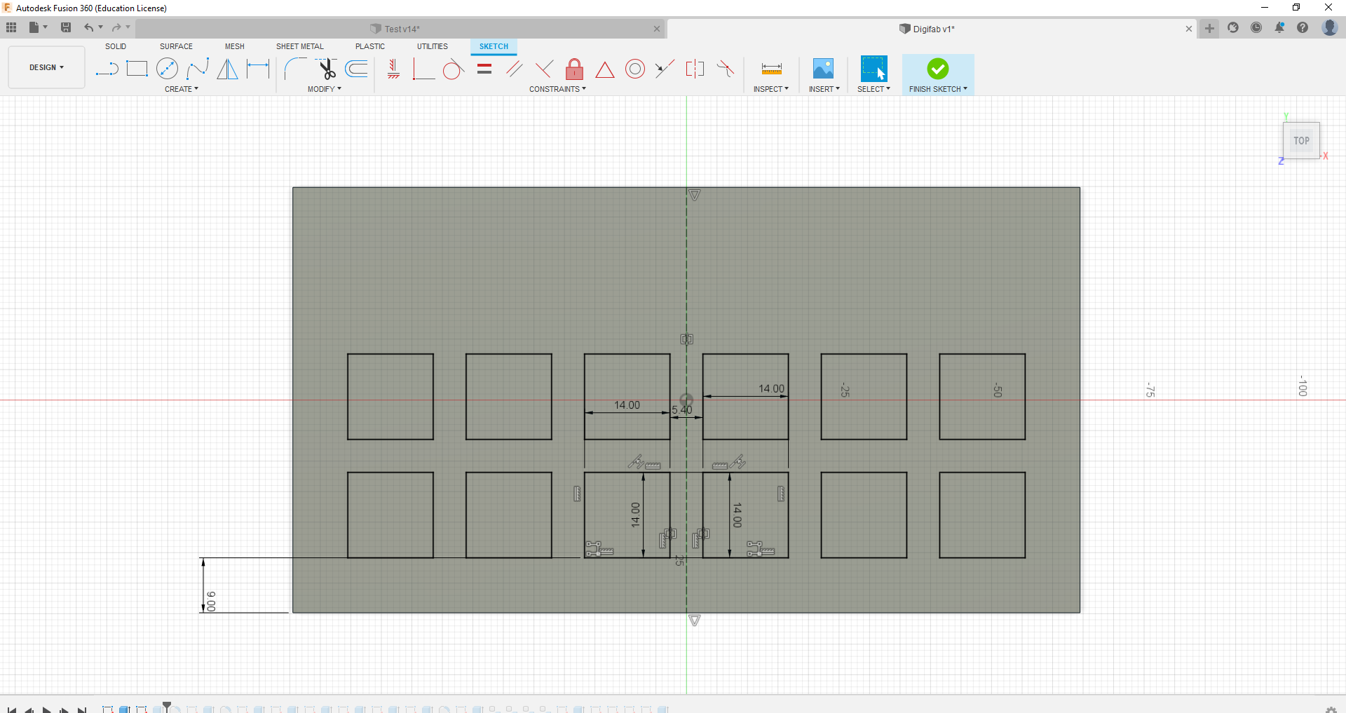
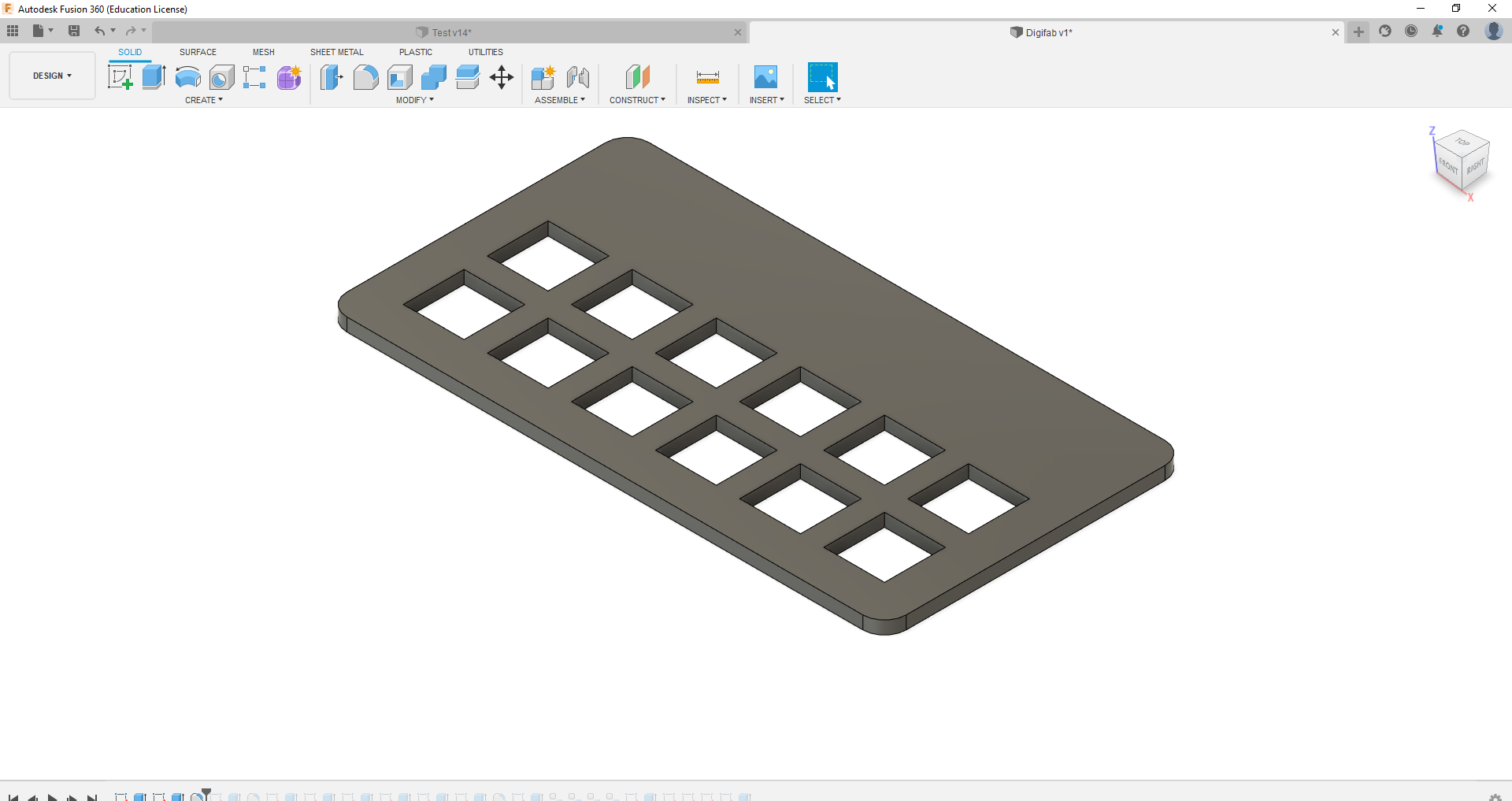
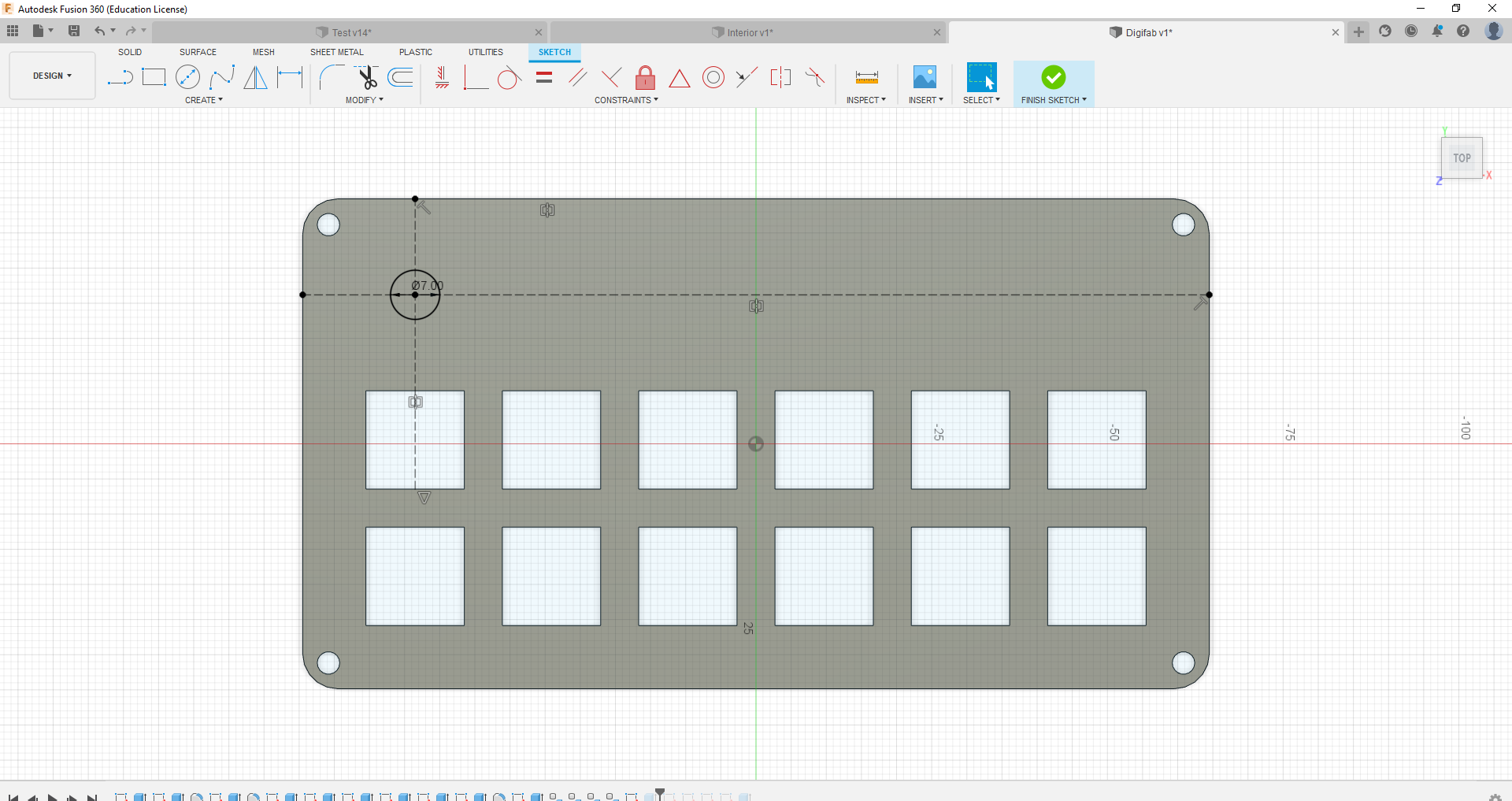
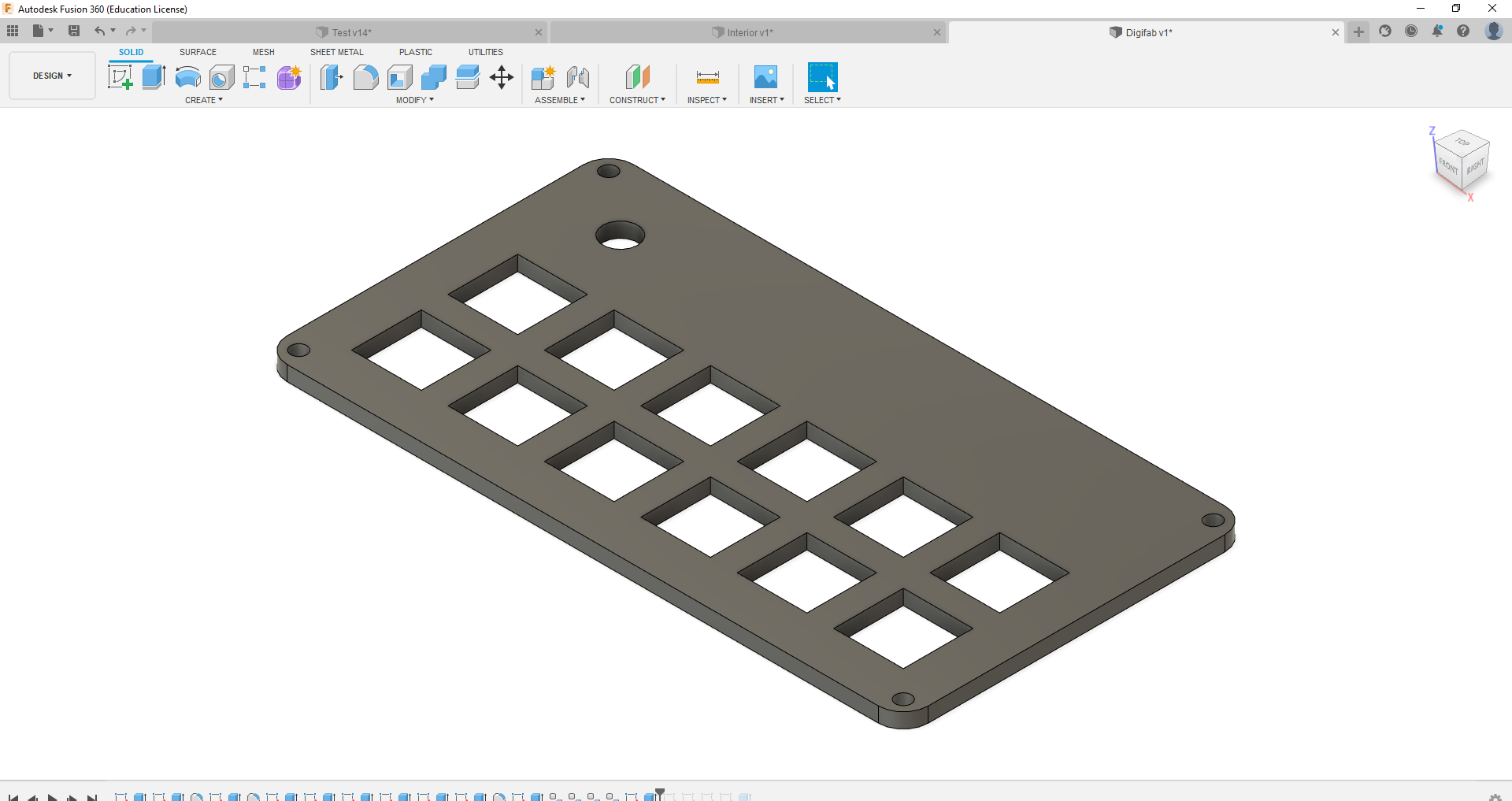
Firstly, I decide to came up with the plate that would hold the switches. This plate would be holding all the switches and the potentiometer(analog knob). For the hole of the potentiometer, I had originally made the hole too small. Hence, I had to make changes to the hole, making it bigger.
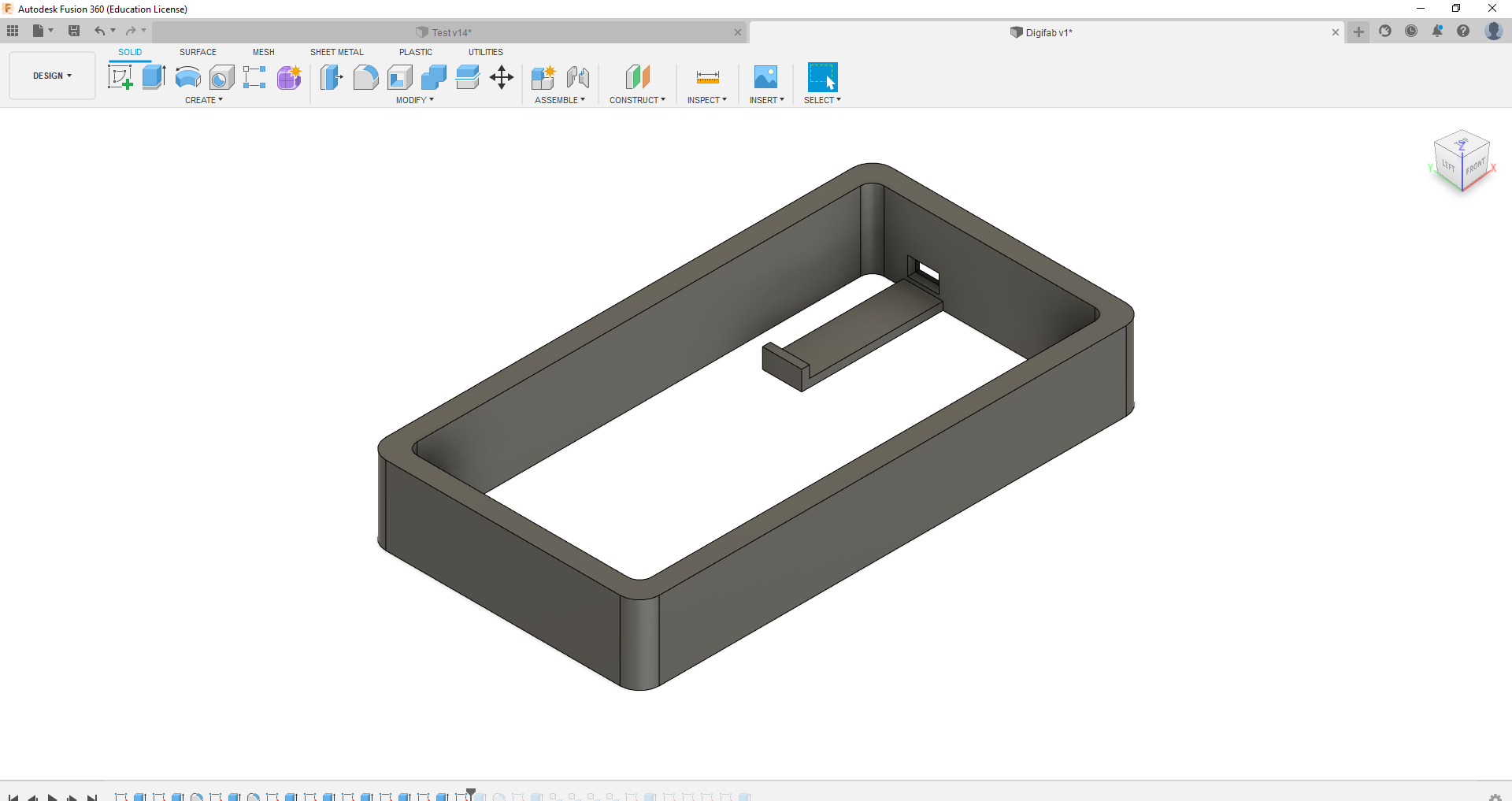
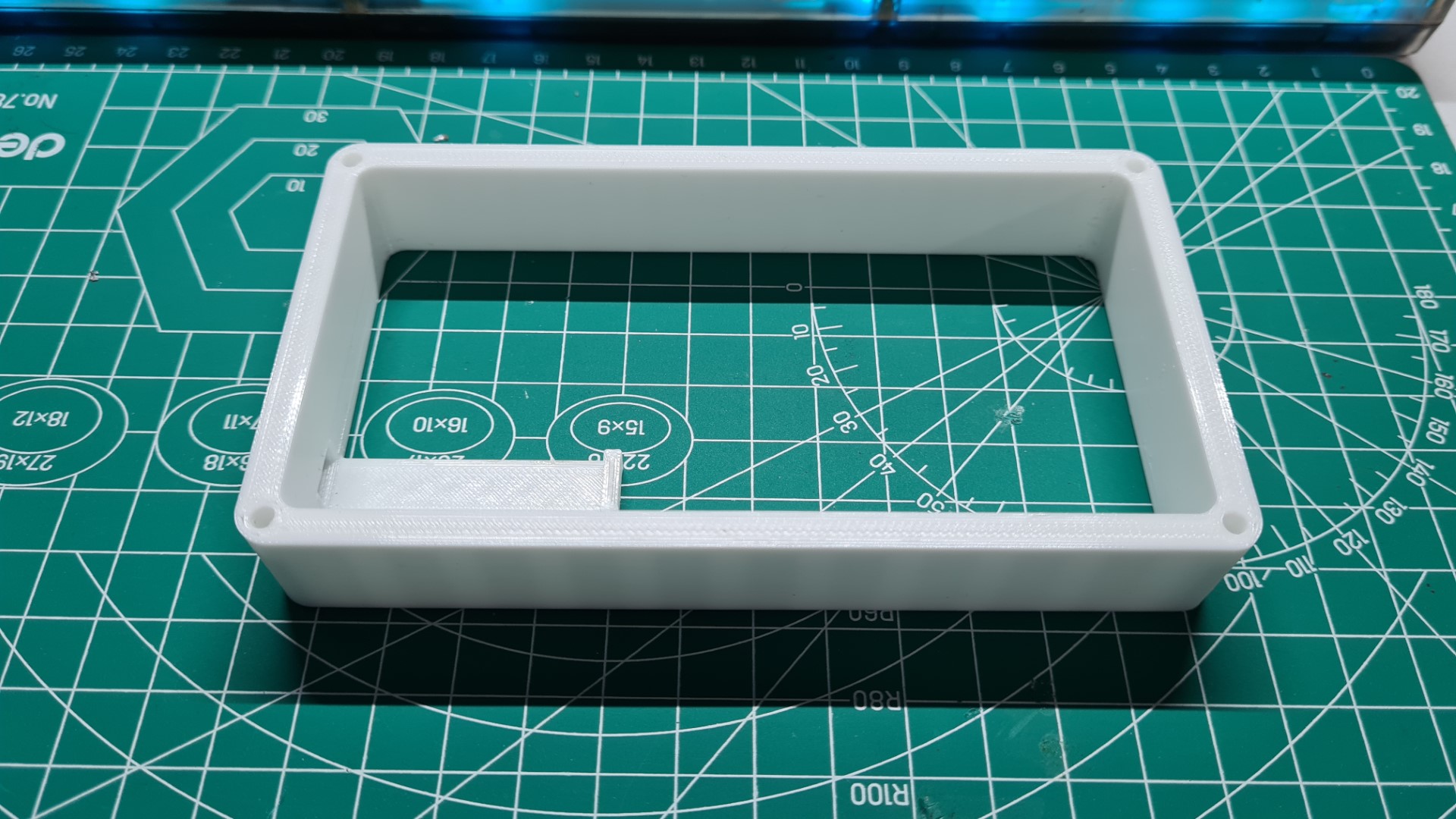
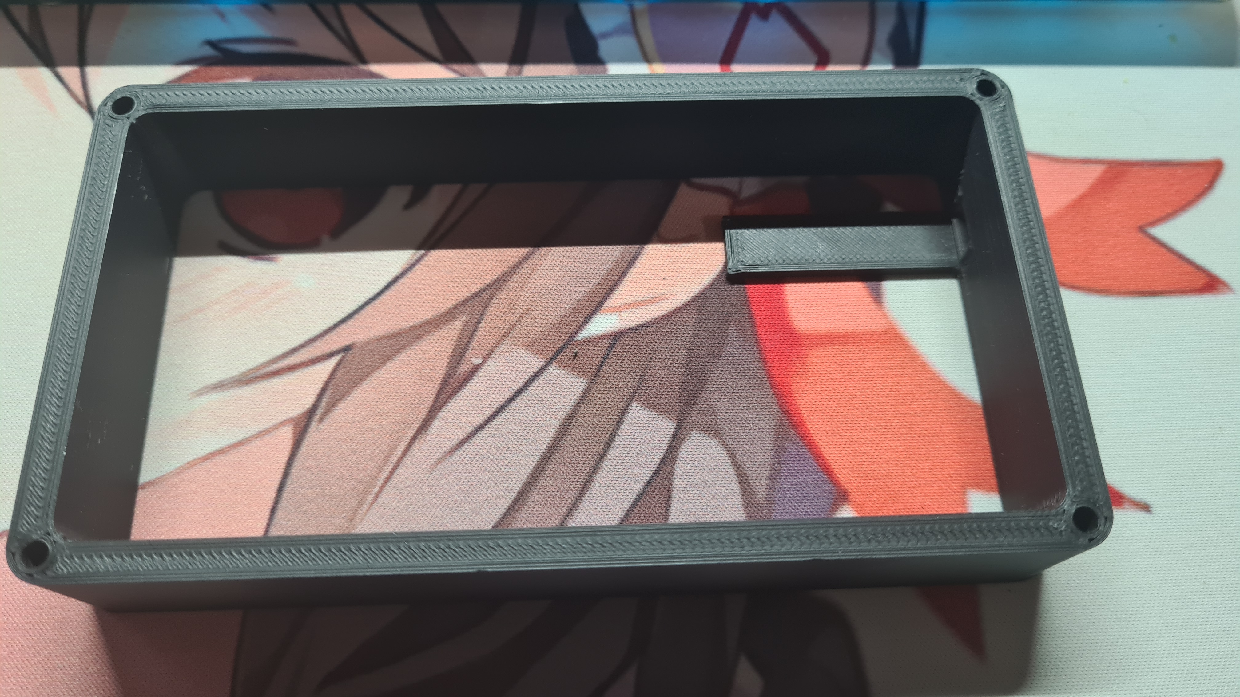
Following the plate, I decided to come up with the main casing of the macropad which would hold the Arduino Pro Micro as well. This case would be the component that would require me to do alot of redesign as I had forgotten to factor in the size of the Pro Micro when designing the mount in the case. When designing the case, I had to accomodate for the amount of wires I would be using later on, hence the case is the thickest component I had to design.
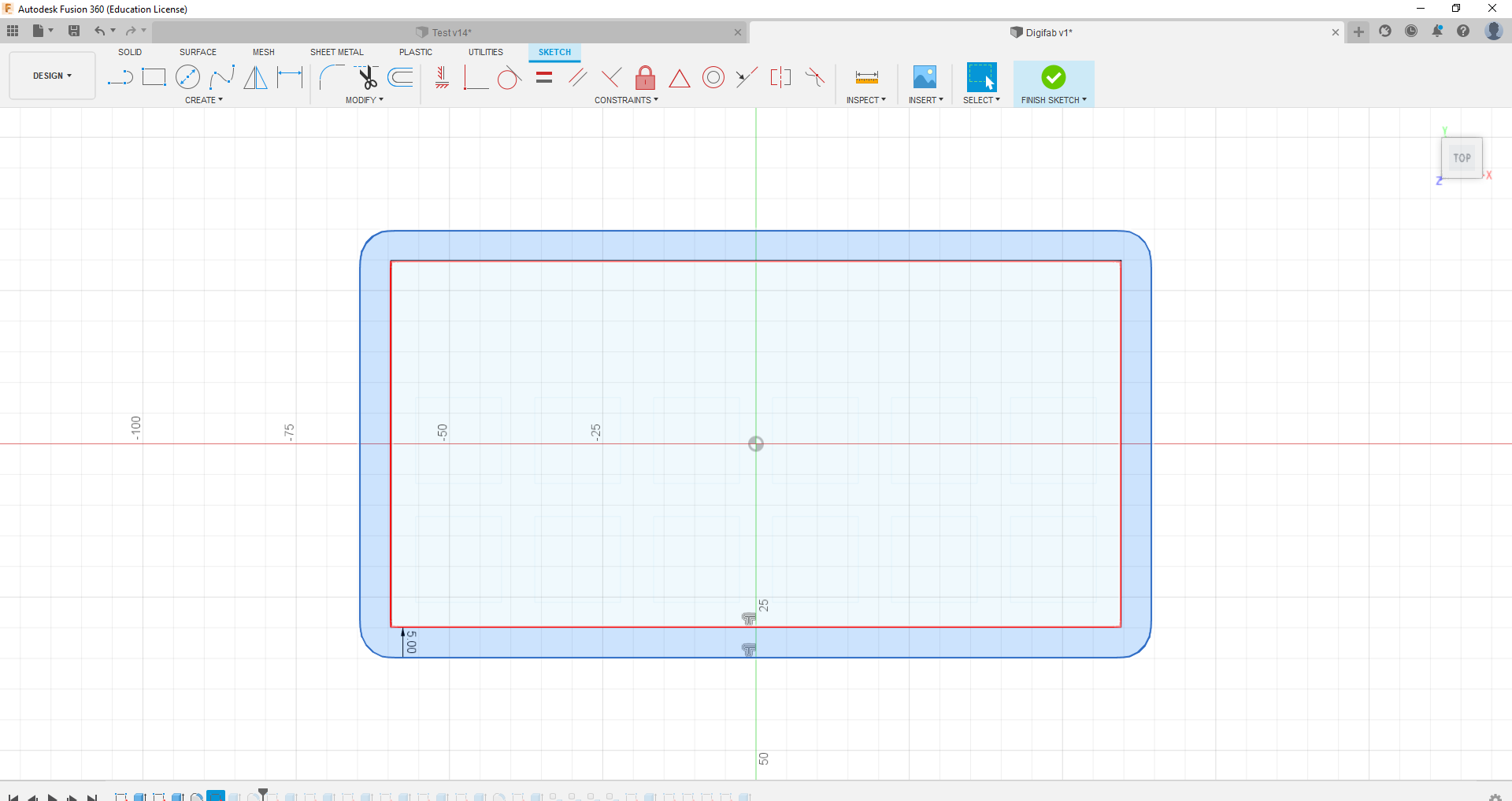
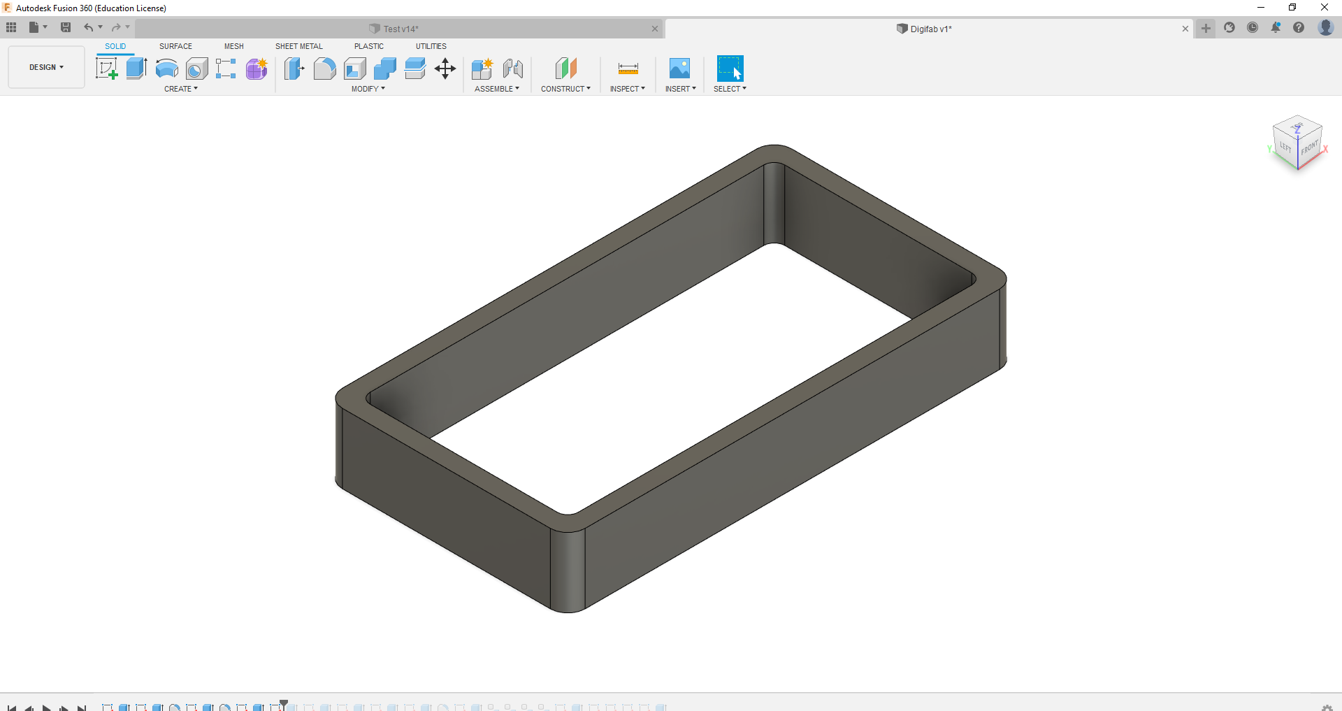
Finally, I made the base and the top rim that surround the switches. I also added in the holes that will be used to secure the whole thing together with screws.
.png)
.png)
.png)
.png)
Final 3D Model
Below is the Final Model updated to match the completed Product. During the fabrication process, some changes were made to better fit certain components which is why the Final Model might look somewhat different in some areas, espeically the pro micro mount.
Interior
Exterior
Laser Cutting
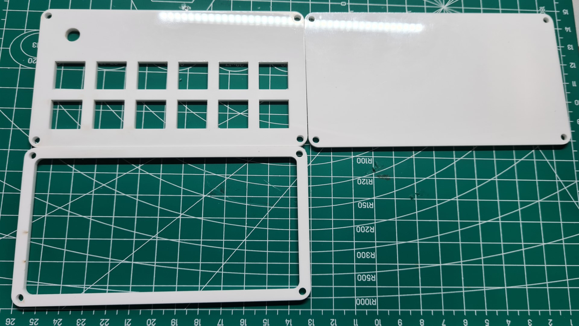
Eventhough changes were made to plate for the switches which resulted in a 2nd plate being cut, the laser cutting process ran quite smooth and all the parts were cut in 1 session.
Laser Cut Parts
3D Printing
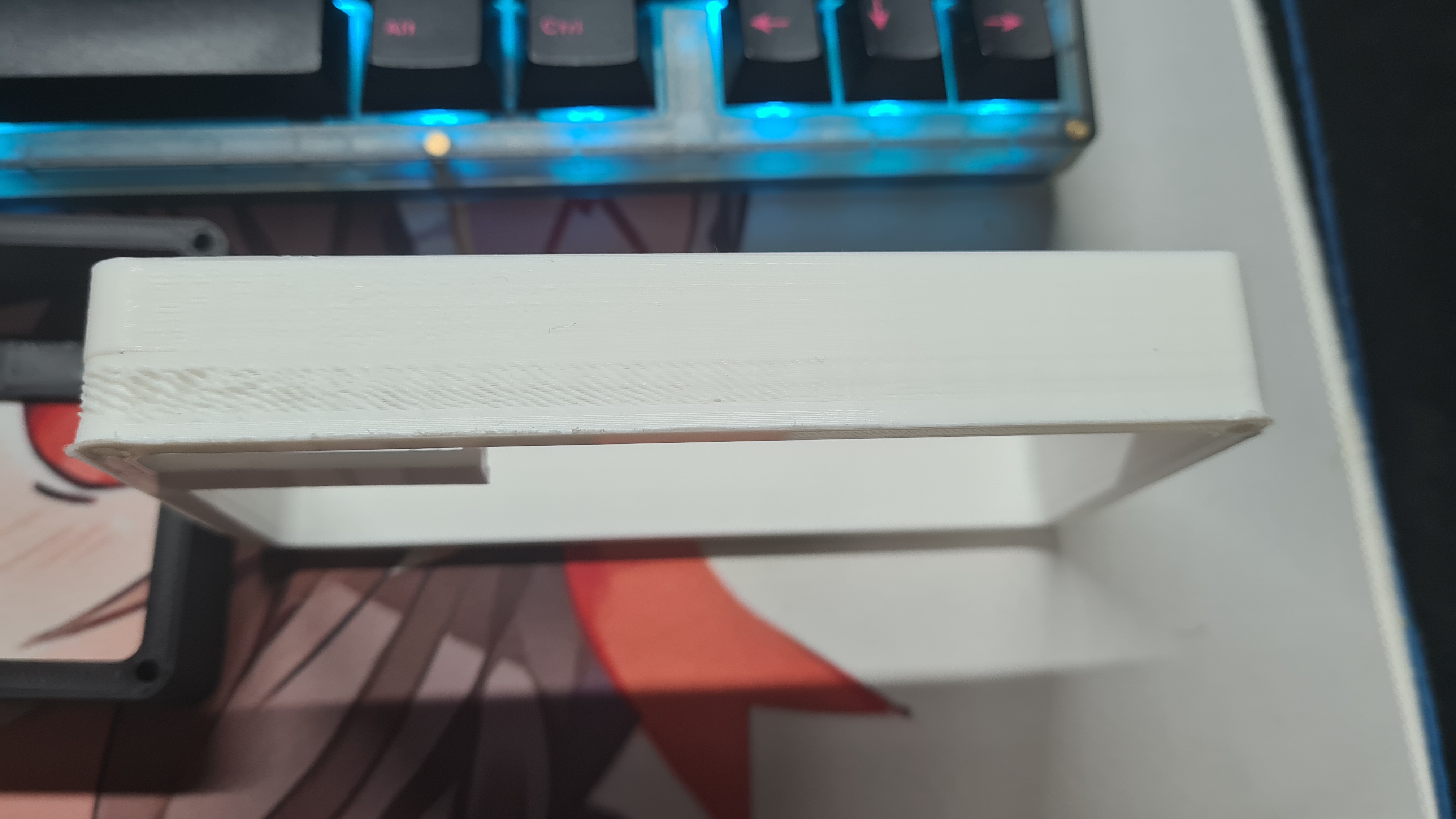
Unlike the laser cutting process, the 3D printing process had more problems, from undersizing the mount to poor print quality. However in the end, I was able to get 1 good print for the case.
3D Prints
Failed Prints
Electronics
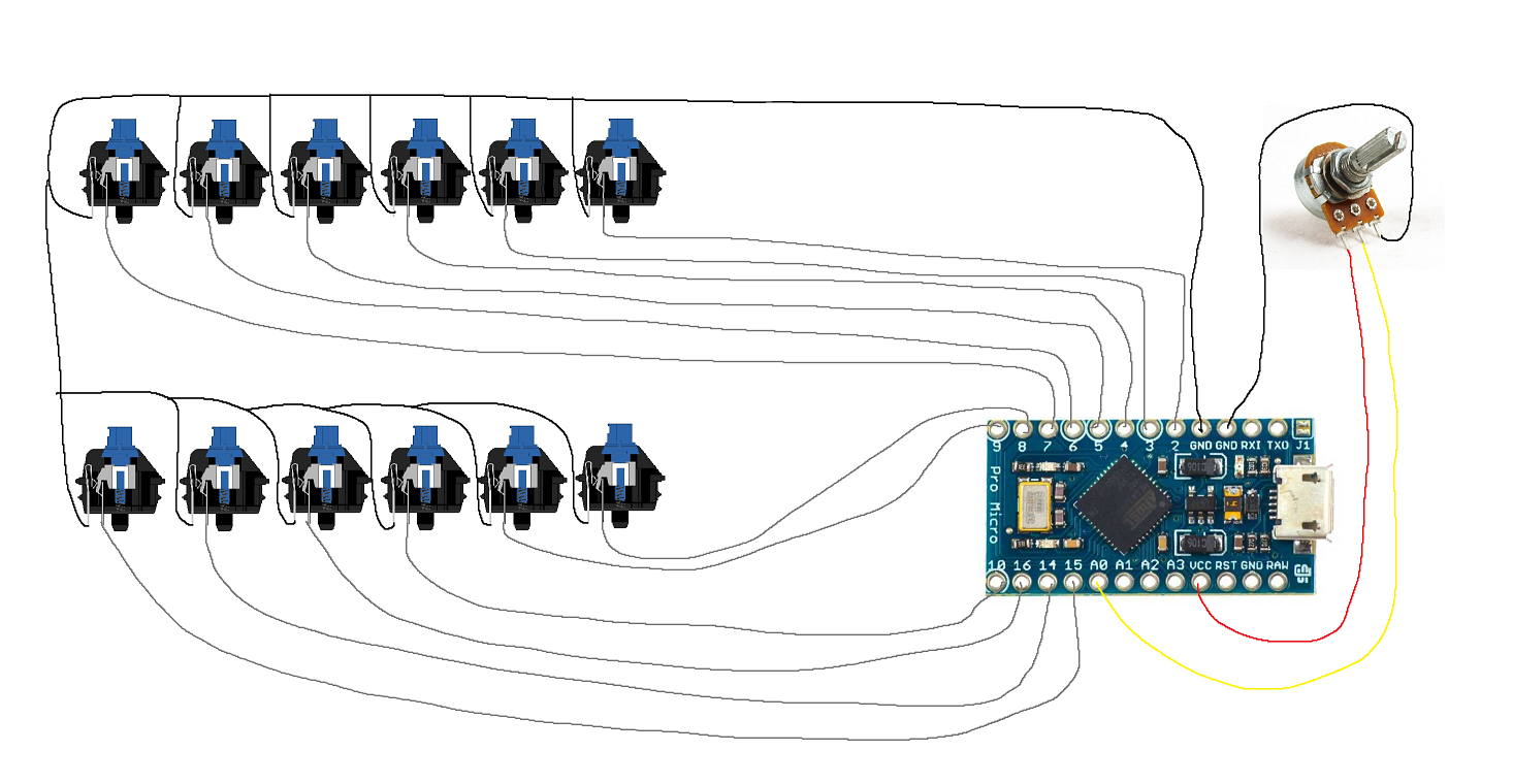
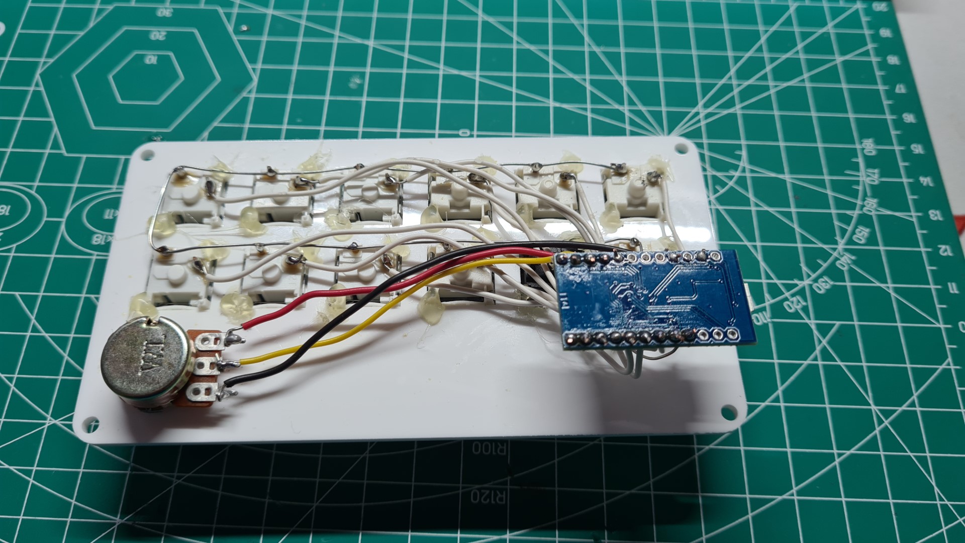
The circuity for this project was not very complicated, it just contain many componnets. Eventhough the connections are very straightforward, it is very repetitive and the number of components requried to solder resulted in hours spent on just soldering.
Planned Circuit
Completed circuit
Code
Setting Variables/Adding Libraries
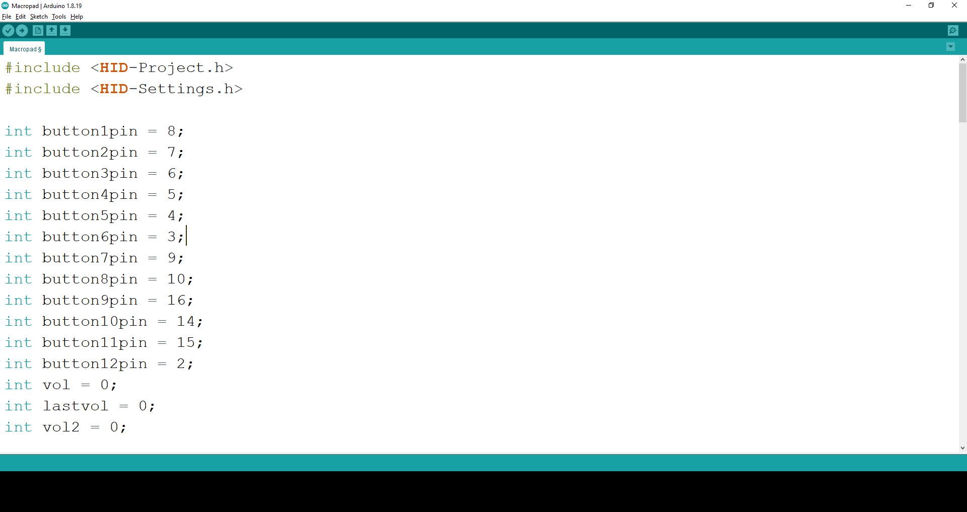
Setting up Pins
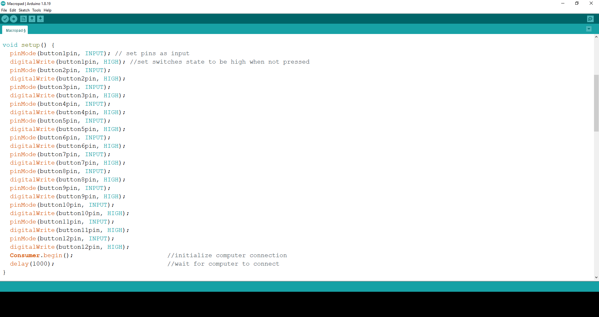
This part of the code is used to set the pins to start at "HIGH" state, at the same time set the pins as input. This part also intitates the connection with the computer.
Assigning the switches
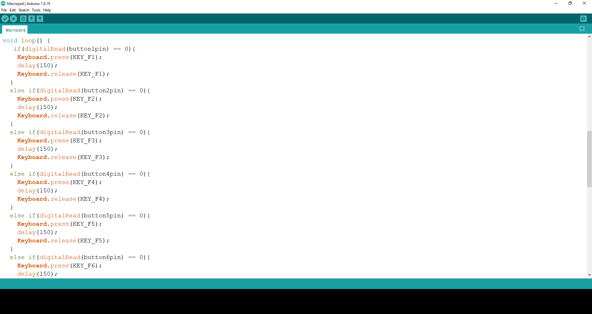
This portion of the code is used to assign what key will be inputed on the computer when the switches are pressed. This code is repeated for each of the 11 keys used to input F1 - F11.
Coding the Analog Input
This code is used to set the potentiomer to adjust the volume of the computer. The code takes the range of values that the potentiometer will output and sets it to 100 steps to represent volume 0 to 100, this is then further divided to 50 steps to make the volume increase and decrease more managable. To prevent any sudden or unintended changes, the last key in the macropad must be pressed down before turning the potentiometer when trying to change the volume.
Final Product
Below is the Final Product and a video, showing briefly the design process as well as testing of the macropad.